A rated turn is a two minute turn as indicated by the turn and bank coordinator. It’s very useful in instrument flying. When the turn and bank indicator is coordinated in a rate one turn, it will take 2 minutes to travel 360 degrees. By knowing this information we can use it to get us to a heading that we want.
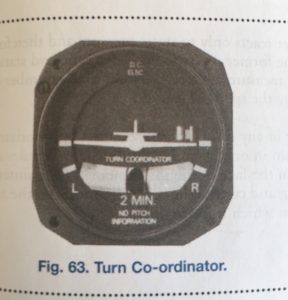
The turn coordinator. Image taken from the From the Ground Up textbook.
The turn coordinator shows a coordinated rate one turn when the wing tips of the miniture airplane touch the lower bands, either right or left depending on the direction of turn, and the ball is in the center. For example, if the wing touches the right tab and the ball is in the middle, if you keep it like this for two minutes you’ll end up on the same heading you started. If you keep it like this for one minute, you’ll end up 180 degrees to the right: in the exact opposite heading on which you started.
This instrument has plenty of practical applications particularly when you are lost or have lost visibility, to help you roll out on certain headings.
Understanding it is important for both the private and commercial flight tests.
For example, you’ve tracked an NDB to a known airport, and now you need to descend to below the cloud base to land at the airport. You are planning to land on runway 35 so you know you need the heading of 350 degrees. Currently you’re on a heading of 050 degrees. Using our turn and bank indicator, we can plan a properly coordinated, descending rate one turn to bring us out of limited visibility and into visual sight of the airport runway.
Use available tools to calculate
Remember that a timed turn is a two minute (120 second) turn that takes you 360 degrees. This means if you’re turning 360 degrees / 120 seconds you’re turning 3 degrees per second. To do the math, make it simple for yourself and count the dashes on your ADF or heading indicator. This will help you minimize workload. It will help avoid getting confused by random arithmetic problems, and allow you to focus on keeping your scan going and flying the airplane safely, your number one priority.
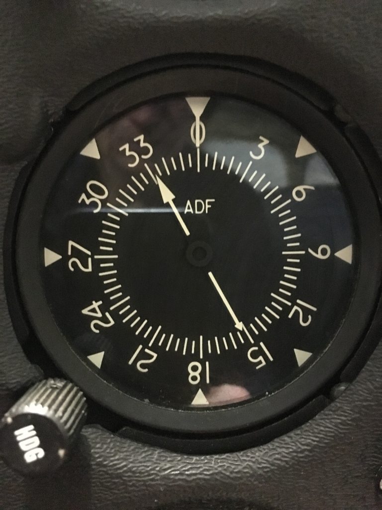
The ADF is marked every 30 degrees: the scale shows 0, 030, 060, 090 and so on. Each of these 30 degree marks is 10 seconds (at 3 degrees per second). So look at the heading you are on and the one you want to go to, and count the seconds in these 30 degree increments.
The Automatic Direction Finder (ADF) in a Cessna 172.
In this case we want to fly from 050 to 350, so we count 90 seconds from 060 to 330. Add another 10 seconds to account for the extra 30 degrees from 050 to 060 and 330 to 350. This means it will take us 100 seconds or 1 minute and 40 seconds in a coordinated rate one turn. Set up your descent and start your turn, and begin your timer.
Once you reach 100 seconds, you should roll out on 350, or close to it. By then you should be able to see the ground and the runway.
The complexity of flying on instruments increases when we simulate a vacuum failure. We loose one especially critical instrument necessary to our flight attitude coordination. The Loss of this instrument in flight can certainly and very quickly and easily turn into a life and death situation.
The purpose of partial panel training
The goal of partial panel simulation is simple: what would happen if you were to have a vacuum failure in the most critical time, when you were in IMC or flying at night? The reason for learning essential basics of instrument flying, including emergencies such as partial panel, doesn’t have to be so complicated as to just needing it to earn your IFR rating for airline flying.
How the vacuum system works
The vacuum system is operated by a venturi which is usually engine driven. The change from higher to lower pressure drives the gyros, so these require some time to spool up and are only accurate after takeoff.
The heading indicator and attitude indicator are vacuum system powered gyros and the turn and bank indicator are electrically powered. So in the event of a vacuum failure, you’ll be able to use your turn and bank indicator to assess when you are wings level and coordinated.
How can we end up with a partial panel in real life flying?
Since in airline flying you’d never encounter this situation, you can experience a vacuum failure at the worst possible as a private or bush pilot, or a pilot for a smaller operation that does bush flying in remote areas. There can be pressure to complete a job, pick up passengers, or get people to a certain destination. You know the weather is going to deteriorate but you decide to go anyway. You fly into the front which has come earlier than forecast and end up in a situation where you are pushing the weather.
Deteriorating weather
Picture you’re on a night cross country flight with little to no great reference to the ground. You’re essentially flying on instruments. Or, you’ve departed during day VFR with a sketchy forecast, and you’ve inevitably flown into an area with low ceilings and decreasing visibility. It starts slowly at first, and before you know it, you can’t see the ground, and you don’t know which way is up. If the worst was to happen and your vacuum system loses suction at this time. You’ll be in deep, trying to keep the airplane under control while trying to figure out what the heck you need to do to get yourself out of this situation.
The first thing you do, of course, is be prepared for this type of worst case scenario by practicing these difficult situations under the hood or better yet, in the simulator. You can even practice at home. Have your instructor create a scenario for you where you are flying to an area with a less-than-ideal forecast tracking different VOR radials and NDBs, and along the way simulate slowly diminishing visibility until you are forced to divert. Enroute to your diversion aerodrome you loose your vacuum system, and are forced to fly without your AI and HI. You need to get to your airport and out of this mess.
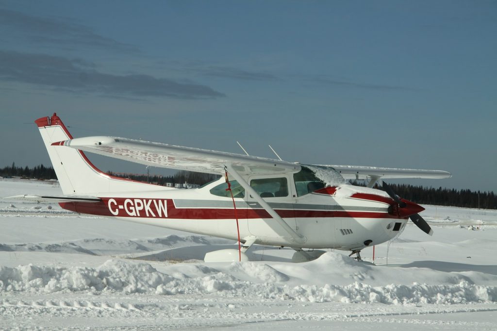
Cessna 182 stuck at a snowy airfield in Northern Alberta.
1. Don’t panic – fly the airplane
The first thing you do if this happens to you is to remain calm, and fly the airplane. Remember to always aviate, navigate and then communicate, in that order. Always focus on flying the airplane before you do anything else. This is especially true when you’ve found yourself in a low visibility situation with limited instruments.
Focus on the instruments that give you the information you need, and start your scan. In the case of full panel flying, this is a lot simpler because you have your attitude indicator at the center of your scan which gives you your most critical information: the position of your airplane against the horizon. Are you nose up or nose down, and are your wings level or are you in a turn?
Start your scan
When you lose your vacuum system, your gyros, the heading indicator and attitude indicator will be immediately unreliable. The major challenge with this is that these two instruments, particularly the attitude indicator, are at the center of our scan. So we have to quickly develop a new method.
The main concept continues unchanged, you continue to control the aircraft with the formula attitude plus power equals performance. The difference is now you have to look at other instruments to get this information. When flying without an attitude indicator, you must determine your pitch by primarily referencing your airspeed indicator, and verifying it with altitude and vertical speed indications.
Control Instruments
Attitude: Airspeed Indicator
Referencing your airspeed indicator for pitch is challenging but doable and requires significant practice to master. My instructor set up a scenario in the sim where my vacuum system failed in cloud while on a low-level diversion to Red Deer. I flew this route a few times and found it took a few minutes to organize the scan before I got the aircraft into a reasonable state of control. The important thing is not to chase the instruments. I did this at first, and found my airspeed all over the place, and then my altitude started to fluctuate and I descended to only 500 AGL.
This happened because I was not allowing the airspeed to stabilize. A certain attitude will give you a certain airspeed. Let it stabilize and reference your altitude and VSI to ensure you’re at a stable straight and level attitude.
Turn information: Turn and Bank Coordinator
Use the turn and bank coordinator to verify that you are wings level. Use the magnetic compass to verify the heading has not changed. Do not fly heading via the magnetic compass, it’s too confusing. The compass works in the opposite direction to turn. So unlike a heading indicator, you turn away from the heading you want to go to, the opposite response that makes sense. The compass also has a significant amount of lag. It’s only reliable to verify that we are on the proper heading, but not looking to it as a control instrument.
Your performance instruments
The performance instruments help you verify the impact of your control inputs are or aren’t what you want them to be. In partial panel flying, they are always attitude plus power equals performance:
Attitude + Power = Performance
Control Instruments + Power = Performance
Airspeed Indicator + RPM = Outcomes shown on the VSI, Altimeter and Magnetic Compass
Turn and Bank Coordinator + RPM = Outcomes shown on the VSI, Altimeter and Magnetic Compass
2. Navigate
Find out where you are by using VORs, NDBs, GPS or ideally combination of those. You can also ask for vectors. This of course bring us to:
3. Communicate
Let air traffic control know you’re in an emergency and ask for help.
Next find out how to use rated turns to get yourself out of cloud and into an airport. Executing a timed turn is a critical skill and becomes very important during partial panel flying.
This video is obviously sped up, but it’s absolutely gorgeous. See the approach to Runway 11 at the Milford Sound airport, MFN, in New Zealand. It is in the fjords of New Zealand, called the Fiordland region, and is used mainly for flightseeing and tourist operators.
Runways 11/29 are 2565 feet long and the elevation of the airport is only 3 meters, or 10 feet above sea level. MFN is a small but very busy airport. This is not the first time a video of an approach and landing in New Zealand is featured in an amazing video – check out the amazing instrument flight into Queensland, also New Zealand. It’s equally stunning!
The highly anticipated NextGen area navigation, a type of RNAV equipment is now available at At Dallas / Fort Worth International Airport (DFW). It has been very successful, allowing the airport to accommodate practically a tripling in departures. In fact, NextGen satellite procedures allow for a 15-20% increase in departures per hour in congested periods.
What is RNAV?
RNAV is area navigation, which allows IFR aircraft to choose any route between a network of navigational beacons for route finding. Rather than flying from beacon to beacon, aircraft can fly any route within the coverage of station-referenced navigation signals. This allows lots of flexibility since aircraft can fly a straight course rather than zigzagging to and from beacons. The beacons are satellite serviced.
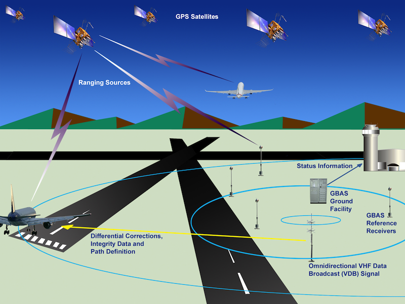
Ground based RNAV is serviced by satellites and onboard technology. Image from faa.gov.
RNAV was introduced in the 1960’s and slowly waned in popularity as airlines began to favour inertial navigation systems rather than ground based navigation aids. RNAV was re-introduced after the massive introduction of satellite navigation. The procedure uses a combination of onboard equipment and satellites to ensure that aircraft follow a precise path and heading. Conventional RNAV procedures begin only once the aircraft is airborne, while ground based RNAV, such as the one at DFW, begins on the runway.
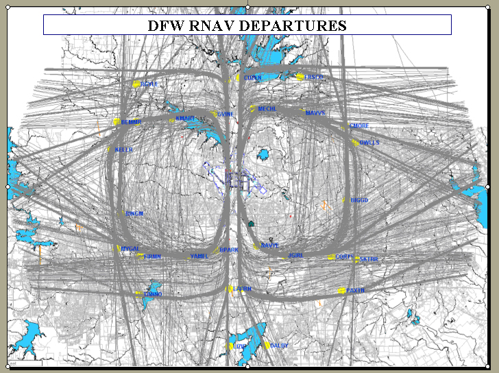
RNAV departures at DFW. DFW is the fourth busiest airport in the world by aircraft movements. Image courtesy of Boeing.com
How does NextGen work?
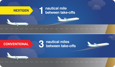
NextGen starts working on the ground and only requires one nautical mile between departing aircraft. This system begins service on the runway and is provided to the aircraft as it enters high altitude airspace.
Conventional departure procedures, which require more correspondence between the pilots and ATC, call for separation minimums with departing aircraft of 3 nautical miles between take-offs. Those two miles make a difference. American Airlines, who is responsible for 80 per cent of DFW departures, has already reported an increase in throughput of between 10 – 20%.
Most aircraft use RNAV when they are in the air, however the difference at DFW is that RNAV navigation starts on the runway – on the ground, and not in the air. Hence separation is provided before takeoff allows smaller separation minimums to be observed.
In a congested airport like DFW, this really does make a difference. Less aircraft idling and waiting means fuel savings. Approximately 95% of the commercial jet fleet at DFW is equipped to fly RNAV. DFW is one busy airport – as you can see in the image above. In fact, it is number four in the world for aircraft movements, tallying 650,124 movements in 2012.
What are the benefits?
RNAV allows to conserve flight distance, save fuel, reduce congestion as well as allow flights into airports without beacons. RNAV beginning on the runway offers more time and fuel savings, for example, American Airlines has reported an annual fuel savings of around $10-12 million at DFW due to these improved RNAV technology. This will also improve local air quality.
Reduces possibility of verbal communication error
Since RNAV provides a pre-determined flight track programmed in the aircraft’s flight management system, this means less communication with pilots and ground controllers. This is more expeditious than the regular procedure, in which the controller gives the pilot a heading and the pilot will acknowledge it verbally. This gives less chance for a miscommunication to happen, and the FAA reports it has already decreased pilot-controller verbal correspondence by over one third. This gives controllers more time to concentrate on traffic that requires more complicated instructions.
This is a very popular technology that will likely be introduced at many congested airports worldwide.
Canadian Domestic Airspace is divided into seven classification, each identified by a single letter. The rules governing each airspace depend on it’s classification and not by which name the airspace is commonly known. Control l or terminal areas can be classified B, C, D or E but weather minimums for flying are still related to the common name of the controlled or uncontrolled airspace.
The classification, as you may remember from ground school, looks sort of like an upside down layer cake, where the smallest classifications are nearer the ground and larger zones extend upward.
Class A
This is all controlled high level airspace, only IFR flight is permitted. It spans from FL180 to FL600, inclusive. ATC (air traffic control) is provided to all aircraft, and require clearance to enter.
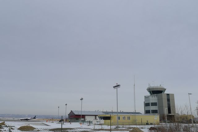
Tower at YBW. Contol zones can be class B, C, D or E.
Class B
In class B airspace, IFR and VFR traffic is allowed. ATC is provided. It includes all controlled low-level airspace between 12,500 and up to, but not including 18,000. VFR traffic must file a flight plan and request a route to enter. A pressure altimeter is required (has to have been certified within 24 months) and a transponder with mode C capability.
Class C
IFR and VFR permitted. VFR must be cleared by ATC to enter. Terminal control areas and associated control zones may be classified Class C when the appropriate ATC unit is not in operation. A 2 way radio and transponder with mode C capability is required. In case of a communications failure, squawk 7600. Otherwise, VFR traffic must use 1200 on transponder.
Class D
Both IFR and VFR traffic are permitted, and VFR must establish radio communications with ATC. ATC separation is only provided to IFR traffic. Terminal control zones can be classified Class D, and if there is no ATC they will revert to Class E.
Class E
This class of airspace exists when none of the requirements for neither A, B, C, D are met. Both IFR and VFR are permitted but again, ATC separation is only provided to IFR traffic. There are no special requirements for VFR traffic. Low level airways, control area extensions, transition zones and control zones without an operating tower may fall into this category.
Class F
Forbidden or advisory airspace.
Class G
Does not fit into any of the other airspace categories, and ATC has neither the responsability nor obligation to manage traffic. This is uncontrolled airspace. Low level air routes and aerodrome traffic zones fall into this category.
It’s easy to forget these classifications. A useful mnemonic to remember these types of airspace and what is associated with each will help you remember!
A = Airliners. IFR only. Between 18,000 and 60,000 feet.
B= IFR. Between 12,500 and 18,000
C = Clearance required to enter
D = Dialogue is required. Do not enter before talking to a controller.
E = Easy for VFR, Everyone gets home from this class of airspace, no need to talk to controllers.
F = Forbidden, or Fancy – special use airspace.
G = General uncontrolled airspace.
And of course, the U.S. has their own unique system of classification. Information on the U.S. system can be found in From the Ground Up.
It’s springtime, and out here in Alberta the weather is all over the place. From clear, sunny, calm days arrive strong wings, snow, sleet, rain, low ceilings and all sorts of weather, signifying change of seasons. Yesterday for example we did not have VFR weather here. In fact, with a visibility of 1/2 SM, vertical visibility of 500 feet and snow at CYBW we have LIFR, or low instrument flight rules conditions – this means ceilings and visibility conditions below IFR minimums. Ceiling is below 500 feet and visibility is less than 1 SM.
There are two kinds of flight rules, visual flight rules and instrument flight rules. VFR stands for visual flight rules and means the pilot flies the aircraft with visual reference to the ground, using landmarks, roads, avoid aircraft in the vicinity, avoiding terrain and obstacles. The pilot must know where they are at all times and maintain visual contact with the ground at all times.
Weather minimums have been established to allow the pilot to fly VFR. These are listed in the table below:
VFR Weather minimum. Image from the AIM and Langley Flying School.
As long as these minimums are observed, the pilot can fly VFR. Remember that some types of airspace do not allow VFR traffic, or VFR traffic must seek permission in order to enter certain kinds of airspace.
Also applying to VFR traffic are altitude rules. VFR traffic flying at 3000 feet AGL or higher must follow specified rules about altitude depending on direction flown. Cruise altitude is based on magnetic track. The altitudes are:
For headings: 180 degrees – 359 degrees = EVEN thousand + 500 feet
VFR traffic is not allowed to fly over cities (built up areas) lower than 1000 AGL, and should not descend below 500 feet AGL during flight – of course this does not apply to special flights (police, ambulance) nor during take off or landing phases of flight. This explains why the traffic helicopter always seems to buzz my house!
VFR traffic can use instruments to operate, but are not allowed to rely on them unless they have an IFR rating, and are flying IFR.
Pilots flying VFR are allowed to start a flight that is initially VFR but changing to instrument meteorological conditions (IMC), and where visual flying will not be encountered anymore. The best thing to do in this situation as a VFR pilot is to either fly straight and level until the conditions improve, or complete a 180 degree turn where you came from to return to visual conditions. Also, if you are near a control zone, you can request SVFR – special VFR. The aerodrome must have at least 1 mile visibilty and you must remain clear of cloud.
If you are not near a control zone and encounter these conditions, you are forced to fly IFR. The best solution is to avoid IMC if possible unless you are IFR rated.
Another solution is to fly VFR “over the top” or OTT. This is a special rating that private pilot license holders can get to fly over cloud cover, maintain visual contact with other airplanes flying IFR while giving VFR pilots greater flexibility. This rating can be added to your PPL with 15 hours of flight training.
Flying out CYBW, Springbank airport which is number 6 for aircraft movements in Canada. We live near the rocky mountains of Alberta and are obsessed with mountains and aviation!
>>Read More >> Contact me