The relationship between stalls and airspeed is often misunderstood. It is not actually the airspeed of the aircraft that will determine when the wing will stall, but rather the angle of attack.
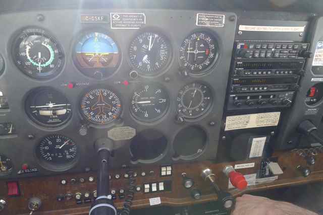
Stall recognition is generally taught with reference to airspeed only. Students are taught to pull up to stall the aircraft and continue doing so, watching the airspeed bleed off, watching the needle go from the green arc, through the white arc where this ends, and the airspeed at which that aircraft (in that particular configuration) is known to stall. Instructors drill into us the importance of angle of attack, and that the aircraft can stall at almost any airspeed. In fact, my instructor and I stalled the aircraft at full power settings. It was surprising and intense, and very important to recognize that this can happen.
There is no instrument to show the relationship between angle of attack and airspeed determining stall due to the complex forces that determine when an aircraft will stall, including weight of aircraft, load factor, the aircraft’s center of gravity, and other factors such as altitude, temperature, aerofoil contamination (frost or ice on wings) and turbulence. The airspeed indicator alone cannot measure when a stall will occour.
Your POH will give you stall speed with flaps up and flaps down configurations, for a certain weight. We learn in ground school that stall speed increases with weight, forward center of gravity (which acts like an increase in aircraft weight), load factor (such as in a turn) and when there is surface contamination. Once you know the basic stall speeds, it is up to you, the pilot, to be able to recognize when you are increasing or decreasing the stall speed.
It’s not the airspeed, it’s angle of attack
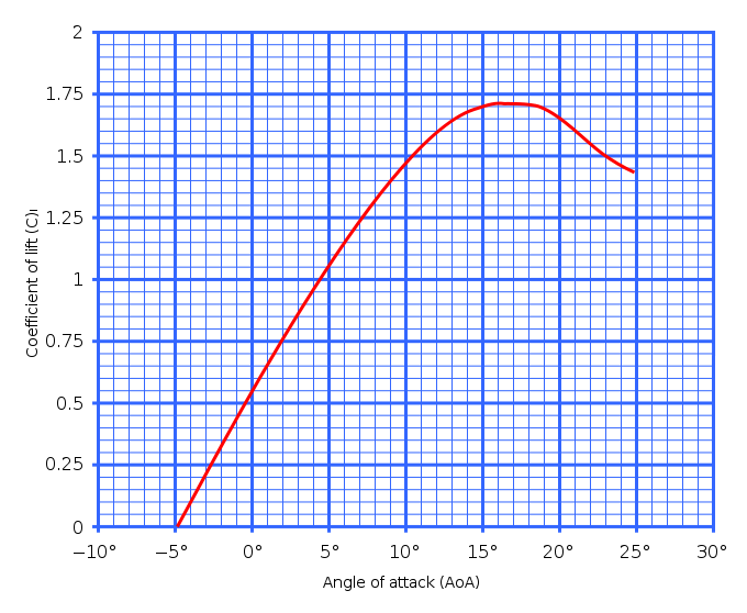
Angle of attack is the angle at which the relative airflow meets the wing. This is what determines when a wing will stall. It’s important to understand relative wind – this is the way the air flows over the wing – when this is disrupted, air can no longer flow the way it’s designed to over the wing, and lift decreases. The critical angle of attack is reached when the maximum lift coefficient is obtained, after which lift will drop off when the angle is exceeded, and the aircraft will loose lift. After the critical angle of attack is reached, the aircraft is said to be approaching a stall.
The aircraft will always stall at the same angle of attack, called the critical angle. Many modern jets have an instrument that prevents the pilot from increasing the angle of attack past the critical angle, this is called the angle of attack limiter or alpha limiter.
Dangers of being low and slow
However this type of tool, or similar instrument is not in most general aviation planes. This leads to the pilot having to be very careful in making sure they don’t push their airplanes in into this flight envelope. When is a stall most dangerous? When you are low and slow. Typically, the base to final turn can be very hazardous, and this is corroborated with the amount of stall-spin accidents that happen during this circuit sequence (for general aviation airplanes). On this turn, you are low, and your airspeed is decreasing since you are on approach. When you turn, you increase the load on the aircraft, and if you push it into a stall (say, by executing a steep turn) you can enter a deadly stall-spin from which recovery is difficult due to the proximity of the ground.
![]() Recently I’ve discovered the aircraft manufacturer Icon Aircraft. This company has created an angle of attack instrument for general aviation airplanes. This instrument measures angle of attack and presents it to the pilot showing when they are flying within the proper range. This is a very interesting development that should go a long way into increasing safety.
Recently I’ve discovered the aircraft manufacturer Icon Aircraft. This company has created an angle of attack instrument for general aviation airplanes. This instrument measures angle of attack and presents it to the pilot showing when they are flying within the proper range. This is a very interesting development that should go a long way into increasing safety.
I recommend watching the video about the concept below. Very cool!